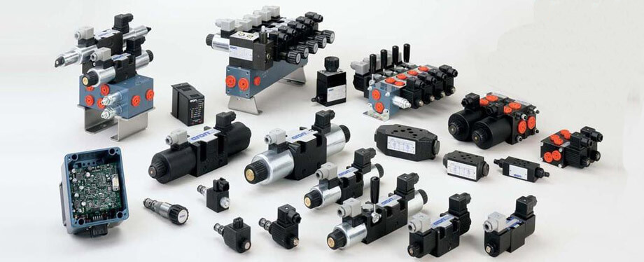
Hydraulic valves are automated components which controlled the pressure, flow and direction of a liquid, which is actuated by hydraulic solenoids. There are different categories to classify hydraulic valves, and different types of hydraulic valves use different types of hydraulic solenoids as their actuators. Based on the control methods, there are manual hydraulic valves, electrical control hydraulic valves, pilot-operated hydraulic valves. Based on different functions, there are hydraulic flow valves (such as throttle valves, flow control valves, diverter valves), hydraulic pressure valves (relief valves, pressure reducing valves, sequence valves, unloading valves), hydraulic directional valves (solenoid directional valves, manual directional valves, check valves, pilot operated check valves). Based on the installation ways, there are plate valves, tube valves, sandwich plate valves, threaded cartridge valves, cover valves.
Sometimes, you may find some hydraulic valves with similar shapes, but based on its mode of actions, they may have different functions. In the following articles, we will introduce several different types of hydraulic valves.
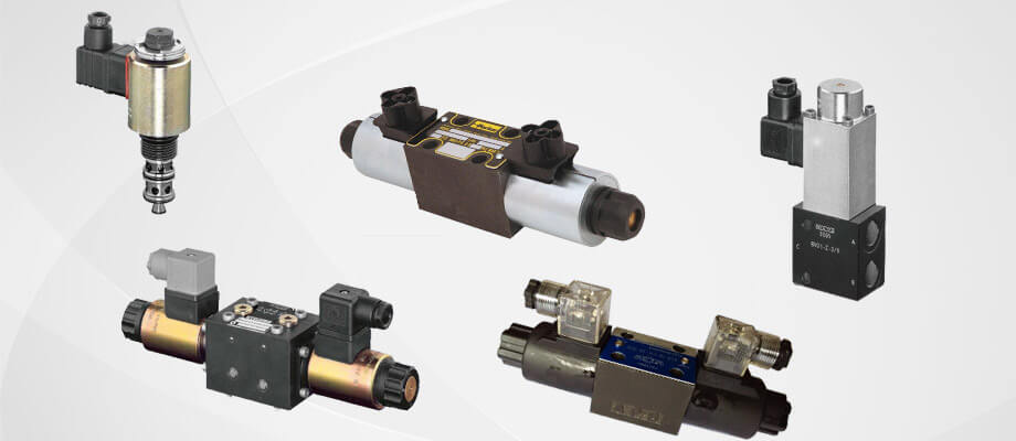
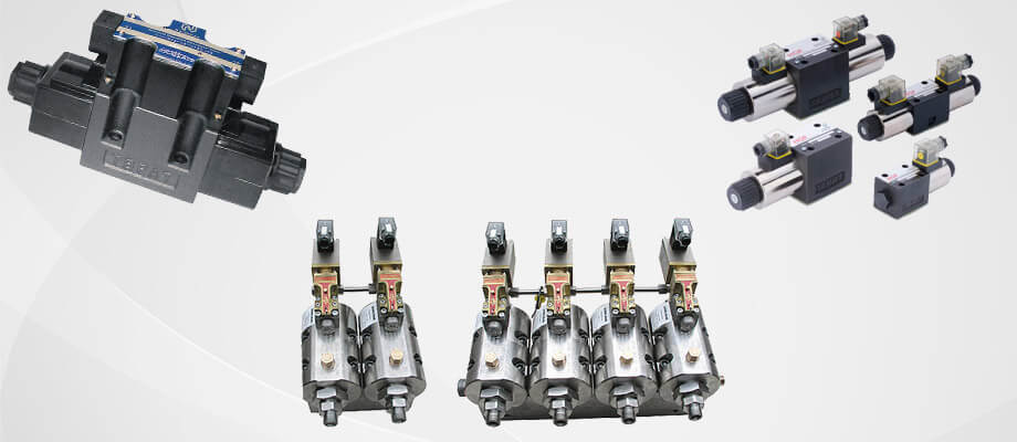
Electromagnetic Directional Valve
Electromagnetic directional valve is actuated by on-off solenoids. The force of on-off solenoid can push the valve spool so that the valve can control the direction of the fluid flow. There are two typical structures of solenoid directional valve, hydraulic directional slide valve, and hydraulic directional ball valve. Normally, when we say solenoid directional valve, it means the hydraulic directional slide valve, hydraulic directional ball valves are normally called as directional seated valve. There are many different types of Electromagnetic directional valves. Based on the numbers of valve service tapping position and NG, there are 2-way NG3 directional valve, 2-way NG4 directional valve, 3-way NG4 directional valve, etc. Based on the structure of the solenoid the valve used, there are wet valve and dry pipe valve.
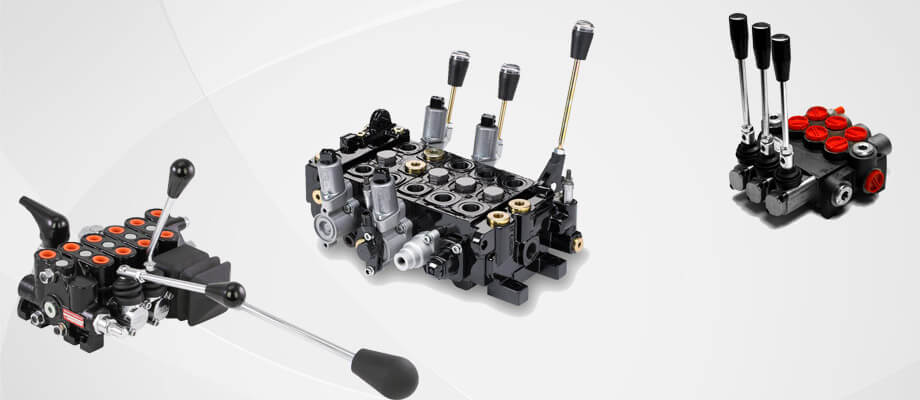
Manual Directional Valve
Manual directional valve is the valve that can switch the directions by hand lever. It has been widely applied in hydraulic systems to control the direction shift, cut-off of the oil fluid. The most common manual directional valve structure is the 3-way NG4 directional valve.
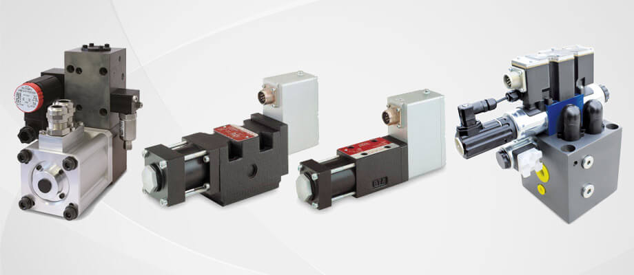
Hydraulic Proportional Valve
Electro-hydraulic proportional valve is actuated by the installed proportional solenoids. According to the input voltage signal, proportional solenoids will respond appropriate actions, which cause the displacement of the valve spool. Therefore, the opening size of hydraulic proportional valve changes and the rated output flow can be controlled. Also, the feedback of proportional valve spool displacement can be realized in the form of mechanical, hydraulic, electrical, etc. Electro-hydraulic proportional valve has been widely used in different hydraulic systems as it holds the advantages of various species, easy assembly, high control accuracy, strong antipollution ability, etc.
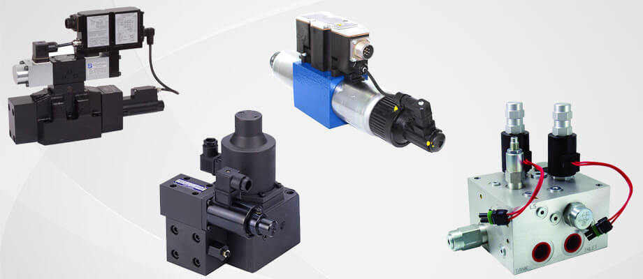
Hydraulic Servo Valve
Hydraulic servo valve mainly refers to electro-hydraulic servo valve, which is the core controller of electro-hydraulic servo system. After the servo valve receives electrical analog signals, the corresponding flow and pressure have been exported. It is not only an electric and hydraulic transform component, but also a power amplifier, which turns the low power electrical signal into high volume hydraulic energy (flow and pressure). In electro-hydraulic servo systems, it connects the electrical part and hydraulic part realizes the transformation between the electrical signal and hydraulic signal, and the amplification of hydraulic.
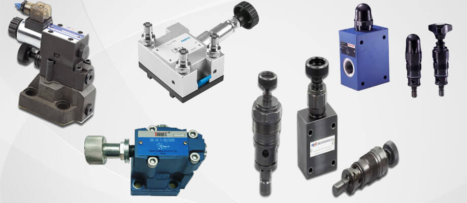
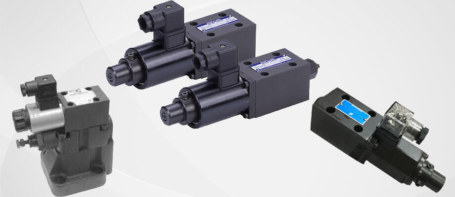
Hydraulic Relief Valve
Hydraulic relief valve is also known as hydraulic overflow valve. When a hydraulic relief valve is working, it controls and adjusts the pressure of hydraulic oil by the pressure of the spring. When the pressure of hydraulic oil is lower than operating pressure, valve spool is pressed to the hydraulic oil inlet by the spring. When the pressure of hydraulic oil is higher than operating pressure, valve spool is pushed away by hydraulic oil, and hydraulic oil flows in the valve. It is obvious that as the pressure of hydraulic oil increases, the valve spool will be pushed further, therefore, more hydraulic oil can flow back to the oil box through the relief valve. If the hydraulic oil pressure is lower than the spring pressure, valve spool can seal the hydraulic oil inlet. As the pressure of hydraulic oil from the oil pump is stable, but the pressure of hydraulic oil in the operating oil box must be lower than the oil pump hydraulic oil pressure. So in the actual working process, there will be some hydraulic oil flow back to the oil box through relief valve, in order to keep the balance of hydraulic oil box working pressure.
As you can see, Hydraulic relief valve takes the role of safety protection which can prevent the hydraulic oil pressure of hydraulic control systems from overloading.
Automatic Valves for Hydraulics
Automatic hydraulic valve means the actions of valves depending on the energy of the media itself, not driven by the external force, such as hydraulic safety valves, hydraulic pressure reducing valves, hydraulic check valves, automatic regulating valves, etc. There is a valve plate which is connected to a mechanical spring in check valves, the open and close of the valve plate are caused by the pressure difference between the pressures inside and outside the valves.
Pressure Reducing Valves
The operation of pressure reducing valves also depends on the energy of media itself. It can reduce the inlet pressure level to the needed outlet pressure level, which keeps the outlet pressure stable automatically. From the standpoint of fluid mechanics, for instance, pressure reducing valve is a throttling component which has a variable local resistance. In other words, through the changes of throttling area, the kinetic energy of fluid velocity also changes, therefore, it can cause different levels of pressure loss that achieves the purpose of pressure reducing. After that, due to the adjustment of control system, the downstream pressure wave keeps balance with the spring force, which means the downstream pressure maintain constant within a specified tolerance range.