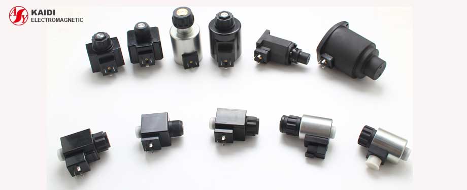
Hydraulic solenoid for control valve is used as basic element of hydraulic valve. The main function of hydraulic solenoid is control fluid or switch. Hydraulic solenoid has great applications like switch valve, proportional valve, and explosion-proof valve. Except for the application, how much do you know about features of hydraulic solenoid? As a hydraulic solenoid supplier, KaiDi has rich experience in processing on-off solenoid, proportional solenoid, explosion-proof solenoid and custom solenoid. We sum the features of hydraulic solenoid up for the solenoid selection.
Hydraulic Solenoid Classification
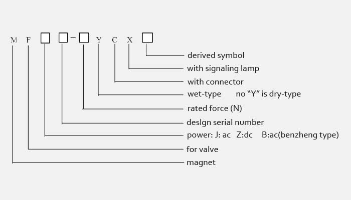
According to different ways, the hydraulic solenoid can be divided into many types, for example, By power: AC solenoid and DC solenoid; By structure: wet-type solenoid and dry-type solenoid
- Wet-type solenoid: it is one-stroke solenoid, and pressure oil is allowed to flow into guide sleeve of solenoid. In the magnetic exciting status, solenoid coil control the iron core from on position to off position. When the solenoid is power off, the iron core get back to the original position.
- Dry-type solenoid: it is one-stroke solenoid, and pressure oil is not allowed to flow into magnetic path or coil of solenoid. As for the working principle, dry-type solenoid is same as wet-type solenoid.
Common terms of hydraulic solenoid
There are common terms for hydraulic solenoid, such as stroke, force, retaining force and related marks
Stroke: Stroke refers to the effective displacement that ensures the output force of solenoid from starting position to closed position.
Force: in terms of the stroke direction, after overcome the friction, solenoid output the effective force called the force. In the range of rated stroke, supply voltage is 85% of rated value, force of solenoid should be not less that the required rated force.
Retaining force: when the solenoid is powered, the effective force is created by iron core at the holding position, which is known as retain force.
Residual magnetic force: when the power is off, the residual force from iron core called residual magnetic force. In general, residual magnetic force of hydraulic solenoid should be less than the 18% of rated force.
Marks:
- Ue – rated voltage
- Ui – rated insulation voltage
- Ie – rated current
- U – relative voltage
- Db – cyclic damp heat test
- CTI – comparative tracking index
- Rm – resistance value
Model and implication:

Key parameter for hydraulic solenoid
| Valve size(mm) | Rated stroke(mm) | Rated force(N) | |
| AC | DC | ||
| 4, 5, 6 | 2.8, 3, 5 | 15~30 | 15~40 |
| 10 | 3.6, 4, 6, 7 | 40~50 | 55~90 |
Characteristics of hydraulic solenoid
Hierachical voltage control
DC (V): 12, 24, 110, 220.
AC 50Hz (V): 110, 220, 380.
Supply voltage
Supply voltage ranges from 85% to 110%.
Structural requirement of hydraulic solenoid
Ageing Resistant & Humidity Resistance
Rubber seal of hydraulic solenoid requires aging resistance. Besides, hydraulic solenoid should have ability to react to hygrothermal environment. Except specific requirement of standard, all solenoid should obey the Db: cyclic damp heat test of GB/T2423.4 – 1993. The top temperature of test reach 40℃, test cycle is 6d. Do the test at the last 1-2h during the stage of low temperature and high relative humidity. The controlled temperature of test chamber is 25 ℃±3, controlled humidity reach 95%-98%, try to avoid the condensation on the solenoid, or experiment result will be affected. Firstly, measure the insulation resistance and its value is more than the value shown in table 2. Secondly, do 1min power-frequency voltage-withstand test, voltage require the value shown in table 6.
Table2: minimum of insulation resistance
| Ui (V) | ≤60 | >60~600 |
| minimum insulation resistance (MΩ) | 0.5 | 1 |
Table6: power-frequency voltage-withstand test
| Ui | AC voltage RMS |
| ≤60 | 1000 |
| >60~300 | 2000 |
| >300~600 | 2500 |
Components’ Requirement
For all components that are made of non-corroding ferrous metals, they must have corrosion protection, except for the pole face and frictional parts. The pole face of magnetic system must be clean and paint preservative oil and grease. Surface of plastic parts is smooth and bright, without crackle and etc.
Electric clearance
The minimum of electric clearance as following table 3
| U (V) | ≤100 | >100~150 | >150~300 | >300~600 |
| minimum electric clearance(mm) | 0.2 | 0.5 | 1.5 | 3.0 |
Creepage distance
The minimum of creepage distance should up to the specification shown in table 4
| Ui (V) | creepage distance (mm) | ||
| materials | |||
| Ⅰ | Ⅱ | Ⅲa, Ⅲb | |
| ≤63 | 0.63 | 0.9 | 1.25 |
| >63~125 | 0.75 | 1.05 | 1.5 |
| >125~250 | 1.25 | 1.8 | 2.5 |
| >250~400 | 2 | 2.8 | 4 |
As for the insulating materials, they can be divided into 4 groups according to the CTI:
Ⅰ: CTI≥ 600;
Ⅱ: 600> CTI≥ 400;
Ⅲa: 400> CTI≥ 175;
Ⅲb: 175> CTI≥ 100.
