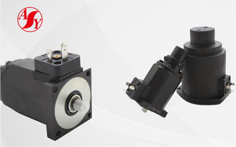
The proportional solenoid is the core component of the proportional valve. The important difference between it and the ordinary solenoid is that the former has a horizontal displacement-force characteristic. Around this characteristic, a lot of proportional solenoid structure schemes have been tested and analyzed. On this basis, we did some summarizations on these important factors that will affect the displacement – force characteristics and the electromagnetic force. In the article Several Suggestions on Improving Displacement-force Feature of the Proportional Solenoid, we briefly introduce the first influencing factor the shape of pole shoe/armature end face. So in this article, we will continue with the last three factors.
The Influencing Factors of Displacement-force Characteristic
The Location of Magnetic Isolation Ring
The horizontal displacement-force characteristic curve of the proportional solenoid in working stroke is composed of two components: end force and additional axial force. The end force is generated when the magnetic inductance line passes through the working air gap into the pole shoe, and the additional axial force is generated when the magnetic inductance line enters the guide sleeve directly from the armature. Changing the magnetoresistance on the magnetic path from armature to guide sleeve can influence the distribution of magnetic inductance line, so as to change the magnitude of the additional axial force and control the shape of displacement-force characteristic curve. However, the magnitude of magnetoresistance is inversely proportional to the sectional area of magnetic circuit, thus we can control the magnetoresistance by adjusting the contact area between armature and guide sleeve (by adjusting the position of magnetic isolation ring), so as to indirectly control the additional axial force.
We can verify the above assumption by conducting experiments on the two structures shown in figure 5. In figure 5a, the armature is in contact with guide sleeve, but in figure 5b, they are not in contact (the magnetic isolation ring blocks them by moving up). As shown in figure 6, we found that the displacement-force characteristic curve of structure 5a was more horizontal. So it can be concluded that in the structural design of proportional solenoid, the armature end (near the side of the air gap) should be kept in contact with the guide sleeve, and the initial contact area should be determined according to the specific size of the solenoid.

Figure 5

Figure 6
The Length of Magnetic Isolation Ring
The structural difference between plan 1 and plan 3 is that the former has a longer magnetic isolation ring, while from the perspective of the displacement-force characteristic curve, the curve of plan 1 is more ideal. Therefore, the longer of the magnetic isolation ring, the better the displacement-force characteristic of the solenoid.
The Working Air Gap Width
As the air-gap permeability is inversely proportional to the width of the air gap, when the air gap is wide, the air-gap permeability will be small. And there will be only a few magnetic inductance lines crossing it. The picture 7and 8 are the structure of proportional solenoid with a wide air gap and its displacement-force characteristic curve. As can be seen from the figure 8, the curve is very horizontal (the slope is very small), but the electromagnetic force is very small (about 5N), which is far from the design requirement (38N). We have tried to increase the electromagnetic force by increasing the number of turns in the coil or the current (i.e., the number of ampere-turns), but the effect is not significant. We find that due to the limitation of the size of solenoid, it is impossible to obtain the estimated electromagnetic force by infinitely increasing the number of the coil turns. From the perspective of electrical safety, it is also impossible to increase the coil current (currently 0.88a), so the best way is to find the optimal balance point between the position of magnetic isolation ring and the width of air gap through experiments, reasonably distribute the distribution of magnetic force lines, so as to obtain a relatively horizontal characteristic curve and at the same time make the electromagnetic force meet the design requirements.

Figure 7

Figure 8
The factors listed above co-exist and restrict each other. It is not easy to design a high-performance proportional solenoid. We need to keep experimenting until we find the optimal solution.
Kaidi is a solenoid coil supplier from China, we provide various kind of solenoid and solenoid coils, such as Rexroth solenoid coil, Yuken solenoid coil, Vickers solenoid coil, Parker solenoid coil and other custom solenoid or solenoid coil according to your drawing or samples. If you are interested in our products, please feel free to contact us.
